Saturday, November 9, 2019

Joystick

               //Joystick Module//

Connection:--  We need 5 connections to the joystick.

The connection are : Key, Y, X, Voltage and Ground.

“Y and X” are Analog and “Key” is Digital. If you don’t need the switch then you can use only 4 pins.

Joystic module arduino Sample code:-

int xPin = A1;
int yPin = A0;
int buttonPin = 2;
int xPosition = 0;
int yPosition = 0;
int buttonState = 0;
void setup() {
  // initialize serial communications at 9600 bps:
  Serial.begin(9600);

  pinMode(xPin, INPUT);
  pinMode(yPin, INPUT);
  //activate pull-up resistor on the push-button pin
  pinMode(buttonPin, INPUT_PULLUP);

  // For versions prior to Arduino 1.0.1
  // pinMode(buttonPin, INPUT);
  // digitalWrite(buttonPin, HIGH);

}
void loop() {
  xPosition = analogRead(xPin);
  yPosition = analogRead(yPin);
  buttonState = digitalRead(buttonPin);

  Serial.print("X: ");
  Serial.print(xPosition);
  Serial.print(" | Y: ");
  Serial.print(yPosition);
  Serial.print(" | Button: ");
  Serial.println(buttonState);
  delay(100); // add some delay between reads
}
Joystick Module


Joystick Module
Joystick Pinout
Joystick Module
Joystick Pinout


Pin Configuration
Pin No.

Pin Name

Description


Joystick Module Features

Two independent Potentiometer: one for each axis ( X and Y)
Auto return to center position
Low weight
Cup-type Knob
Compatible to interface with Arduino or with most microcontrollers


Joystic module Technical Specifications:-

Operating Voltage: 5V
Internal Potentiometer value: 10k
2.54mm pin interface leads
Dimensions: 1.57 in x 1.02 in x 1.26 in (4.0 cm x 2.6 cm x 3.2 cm)
Operating temperature: 0 to 70 °C
Internal Structure
The below image is the internal diagram of a Joystick Module. It consists of two Potentiometer, each for one axis (X and Y). Both 10k potentiometer are independent to move in their particular direction. SW (Switch) pin is connected to a push button internally.

 Joystick Module Internal Structure:-


Where Joysticks Are Used?
When we listen the word “Joystick” we think of Game controllers. If we talk about Electronics there are many useful application of Joystick. These type of module are mostly used in Arduino based DIY projects and Robot Control. As we know, the module gives analog output so it can be used for feeding the analog input based on direction or movement. It can also be connected to a movable camera to control its movement.


How to Use Joystick?

We can use a Joystick Module with Arduino, Raspberry Pi and any other Micro-controllers. We just have to connect the axis Pins VRx and VRy to the ADC Pins of the micro-controller. If you want to use the switch then connect it to the digital Pin of the Micro-controller. Follow the below block diagram to connect Joystick Module with Microcontroller. 

 Joystick Module connection with Micro-controller:-


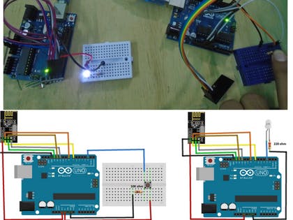
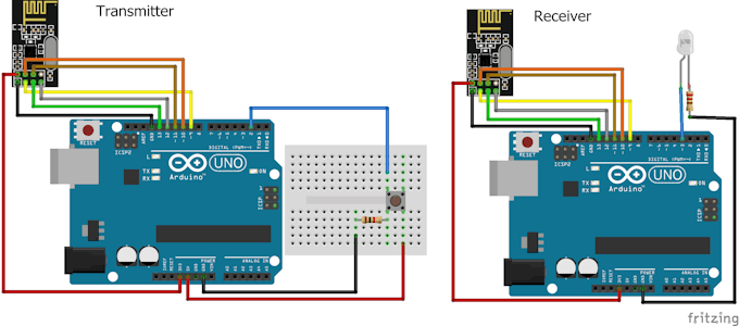
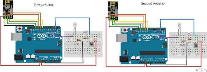
As used in many projects, the interfacing diagram of Joystick Module with the Arduino is given below. It helps you to connect the joystick Module with Arduino and get the analog output based on the direction of movement of Joystick Knob.

 Joystick Module interfacing with Arduino:-


After Interfacing Joystick Module with the Arduino, we will get the analog output. The output range is fixed for each direction. The below image shows, the value of analog output for X and Y axis based on the movement of Joystick Module in all four directions (+X, -X, +Y, -Y). You will also get some analog value when moving the knob diagonally.

 Joystick Module Analog Output:-


Application
Camera Pan/Tilt Control
Game Input/Control
Robot Control
Analog Input of Parameters
Widely use in DIY projects
2D-model

Nrf24l01

The NRF24L01 module is the latest in RF modules. This module uses the 2.4GHz transceiver from Nordic Semiconductor, the NRF24L01+. This transceiver IC operates in the 2.4GHz band and has many new features! Take all the coolness of the 2.4GHz NRF24L01+PA+LNA SMA Wireless Transceiver Antenna and add some extra pipelines, buffers, and an auto-retransmit feature – very nice!
This board features a reverse polarized SMA connector for maximum RF range. And there is PA and LNA circuit on board, with the external antenna it can reach long distance than the one without these parts.
This module comes with the 2.4G antenna (2DB), with 250Kbps transmission rate on open air it can reach the 800-1K meters communication distance.
This wireless Transceiver module is an easy and suitable module if you want to set up your wireless communication system at a low cost!! It can achieve a good balance between wireless transition performance and cost!
You can easily add it with your own MCU/ARM/PIC/AVR/STM32 system! What\’s more, this nRF24L01+ module is designed with the Power amplifier and SMA antenna This allowed you to use the wireless communication up to 1000 meters! (No barrier)

Features :-
  • It uses 2.4GHz global open ISM band, with license free.
  • Transmit power is greater than +20 dBm.
  • Support six-channel data reception.
  • 2Mbit/s speed makes high-quality VoIP possible
  • Multi-frequency points: 125 frequency points meet the needs of multi-point communications and frequency hopping.
  • Low cost: integrated with high-speed signal processing parts associated with RF protocol, such as: automatically re-send lost packets and generate acknowledge signal;
  • SPI interface facilitates the communication with MCU I/O port.
  • Facilitate the development for customers, without development RF part.
  • Software programming is fully compatible with NRF24L01 modules. 
nRF24L01 Interfacing with Arduino | Wireless Communication

nRF24L01 Interfacing with Arduino | Wireless Communication

In the first example, we will send “Hello world” command to blink the LED. In the second example, we will do bidirectional communication.
  • 33,859 VIEWS
  • 8 COMMENTS
  • 45 

In this tutorial, you will learn about nRF24L01 Arduino interfacing with the help of two examples. In the first example, we will send “Hello world” and a command to blink the LED connected to the other Arduino. In the second example, we will do the bidirectional control and will send the command from First Arduino to blink the LED on the second and then we will send the command from second Arduino to blink the LED on the first.

Before going in detail, first have a look at the specification of this module

nRF24L01 Module

The nFR24L01 is a transceiver module which means that it can both send and receive the data.
These modules are very cheap, smaller in size and has a lot of specifications. Some of the specifications of these modules are as follows

Specifications of nRF24L01 Module

  • Power consumption is around 12mA during transmission which is even lesser than the led.
  • It can operate with baud rates from 250Kbps up to 2 Mbps.
  • Its range can reach up to 100 meters if used in open space and with antenna.
  • It can both send and receive the data simultaneously. 
  • Each module can communicate with up to 6 other modules. 
  • It uses the 2.4 GHz band.
  • It can send 1 to 25 bytes of raw data at the transmission rate of 1 MB.
  • It has 125 different channels.

Pinout

The nRF24L01 module works with the Arduino through the SPI communication. The pinout of the module is as follows
The operating voltage of this module is from 1.9 to 3.6V but the other pins are 5V tolerant which means that the other pins can be directly connected to the Arduino.
The MOSI, MISO and the SCK are the SPI pins and these needs to be connected to the SPI pins of Arduino. Different Arduino’s have different SPI pins.
The CSN and CE are for setting the module in active mode and for switching between command and transmit mode. These can be connected to any digital pins of Arduino.
The IRQ pin is the interrupt pin and you don’t have to connect it.

Example 1 - nRF24L01 Arduino Interfacing

In the first example for nRF24L01 arduino interfacing, we are going to simply send the data from one Arduino to other Arduino. When we will press the button connected to the first Arduino, LED connected to the second Arduino will light up.
The circuit diagram for the first example is shown below and the connections are shown below that.

Code for Transmitter

Download the library from here.
#include <SPI.h>
#include <nRF24L01.h>
#include <RF24.h>
RF24 radio(9, 10); // CE, CSN         
const byte address[6] = "00001";     //Byte of array representing the address. This is the address where we will send the data. This should be same on the receiving side.
int button_pin = 2;
boolean button_state = 0;
void setup() {
pinMode(button_pin, INPUT);
radio.begin();                  //Starting the Wireless communication
radio.openWritingPipe(address); //Setting the address where we will send the data
radio.setPALevel(RF24_PA_MIN);  //You can set it as minimum or maximum depending on the distance between the transmitter and receiver.
radio.stopListening();          //This sets the module as transmitter
}
void loop()
{
button_state = digitalRead(button_pin);
if(button_state == HIGH)
{
const char text[] = "Your Button State is HIGH";
radio.write(&text, sizeof(text));                  //Sending the message to receiver
}
else
{
const char text[] = "Your Button State is LOW";
radio.write(&text, sizeof(text));                  //Sending the message to receiver 
}
radio.write(&button_state, sizeof(button_state));  //Sending the message to receiver 
delay(1000);
}

Code for Receiver

#include <SPI.h>
#include <nRF24L01.h>
#include <RF24.h>
RF24 radio(9, 10); // CE, CSN
const byte address[6] = "00001";
boolean button_state = 0;
int led_pin = 3;
void setup() {
pinMode(6, OUTPUT);
Serial.begin(9600);
radio.begin();
radio.openReadingPipe(0, address);   //Setting the address at which we will receive the data
radio.setPALevel(RF24_PA_MIN);       //You can set this as minimum or maximum depending on the distance between the transmitter and receiver.
radio.startListening();              //This sets the module as receiver
}
void loop()
{
if (radio.available())              //Looking for the data.
{
char text[32] = "";                 //Saving the incoming data
radio.read(&text, sizeof(text));    //Reading the data
radio.read(&button_state, sizeof(button_state));    //Reading the data
if(button_state == HIGH)
{
digitalWrite(6, HIGH);
Serial.println(text);
}
else
{
digitalWrite(6, LOW);
Serial.println(text);}
}
delay(5);
} 

Video

Example 2 - nRF24L01 Arduino Interfacing

In the second example for nRF24L01 Arduino interfacing, we are going to do the bidirectional communication. First, we will send the command from the first Arduino to light up the LED connected to the second Arduino and then we will send the command from the second Arduino to light up the LED connected to the first Arduino.

Code for First Arduino

#include <SPI.h>
#include <nRF24L01.h>
#include <RF24.h>
RF24 radio(9, 10); // CE, CSN
const byte addresses [][6] = {"00001", "00002"};  //Setting the two addresses. One for transmitting and one for receiving
int button_pin = 2;
int led_pin = 3;
boolean button_state = 0;
boolean button_state1 = 0;
void setup() {
  pinMode(button_pin, INPUT);
  pinMode(led_pin, OUTPUT);
  radio.begin();                           //Starting the radio communication
  radio.openWritingPipe(addresses[1]);     //Setting the address at which we will send the data
  radio.openReadingPipe(1, addresses[0]);  //Setting the address at which we will receive the data
  radio.setPALevel(RF24_PA_MIN); //You can set it as minimum or maximum depending on the distance between the transmitter and receiver. 
}
void loop() 
{  
  delay(5);
  radio.stopListening();                             //This sets the module as transmitter
  button_state = digitalRead(button_pin);
  radio.write(&button_state, sizeof(button_state));  //Sending the data
  delay(5);
  
  radio.startListening();                            //This sets the module as receiver
  while(!radio.available());                         //Looking for incoming data
  radio.read(&button_state1, sizeof(button_state1)); //Reading the data
  if (button_state1 == HIGH)
  {
    digitalWrite(led_pin, HIGH);
  }
  else
  {
    digitalWrite(led_pin, LOW);
  }
}

Code for Second Arduino

#include <SPI.h>
#include <nRF24L01.h>
#include <RF24.h>
RF24 radio(9, 10); // CE, CSN
const byte addresses [][6] = {"00001", "00002"};    //Setting the two addresses. One for transmitting and one for receiving
int button_pin = 2;
boolean button_state = 0;
boolean button_state1 = 0;
int led_pin = 3;
void setup() {
  pinMode(led_pin, OUTPUT);
  Serial.begin(9600);
  radio.begin();                            //Starting the radio communication
  radio.openWritingPipe(addresses[0]);      //Setting the address at which we will send the data
  radio.openReadingPipe(1, addresses[1]);   //Setting the address at which we will receive the data
  radio.setPALevel(RF24_PA_MIN);            //You can set it as minimum or maximum depending on the distance between the transmitter and receiver.
}
void loop() 
{
  delay(5);
  radio.startListening();                    //This sets the module as receiver
  if (radio.available())                     //Looking for incoming data
  {
    radio.read(&button_state, sizeof(button_state));
    if(button_state == HIGH)
  {
     digitalWrite(led_pin, HIGH);
  }
  else
  {
     digitalWrite(led_pin, LOW);
  }
  delay(5);
  
  radio.stopListening();                           //This sets the module as transmitter
  button_state1 = digitalRead(button_pin);
  radio.write(&button_state1, sizeof(button_state1));   //Sending the data
  }
}


Example 1 TransmitterArduino
    #include <SPI.h>
    #include <nRF24L01.h>
    #include <RF24.h>
    RF24 radio(9, 10); // CE, CSN         
    const byte address[6] = "00001";     //Byte of array representing the address. This is the address where we will send the data. This should be same on the receiving side.
    int button_pin = 2;
    boolean button_state = 0;
    void setup() {
    pinMode(button_pin, INPUT);
    radio.begin();                  //Starting the Wireless communication
    radio.openWritingPipe(address); //Setting the address where we will send the data
    radio.setPALevel(RF24_PA_MIN);  //You can set it as minimum or maximum depending on the distance between the transmitter and receiver.
    radio.stopListening();          //This sets the module as transmitter
    }
    void loop()
    {
    button_state = digitalRead(button_pin);
    if(button_state == HIGH)
    {
    const char text[] = "Your Button State is HIGH";
    radio.write(&text, sizeof(text));                  //Sending the message to receiver
    }
    else
    {
    const char text[] = "Your Button State is LOW";
    radio.write(&text, sizeof(text));                  //Sending the message to receiver 
    }
    radio.write(&button_state, sizeof(button_state));  //Sending the message to receiver 
    delay(1000);
    }
NRF24l01 Library
Optimized fork of nRF24L01 for Arduino & Raspberry Pi/Linux Devices — Read More
Latest commit to the master branch on 12-11-2019
Download as zip

SCHEMATICS

Second Example Circuit Diagram
Nrf24l01 arduino bidirectional bb q1poee9hcv
First Example Circuit Diagram

Soldering iron

Soldering iron A  soldering iron  is a  hand tool  used in  soldering . It supplies heat to melt  solder  so that it can flow into the ...